
How to Read a Schematic for the First Time (Without Getting Lost)
GCSE Courses · July 24, 2026 · 5 min read
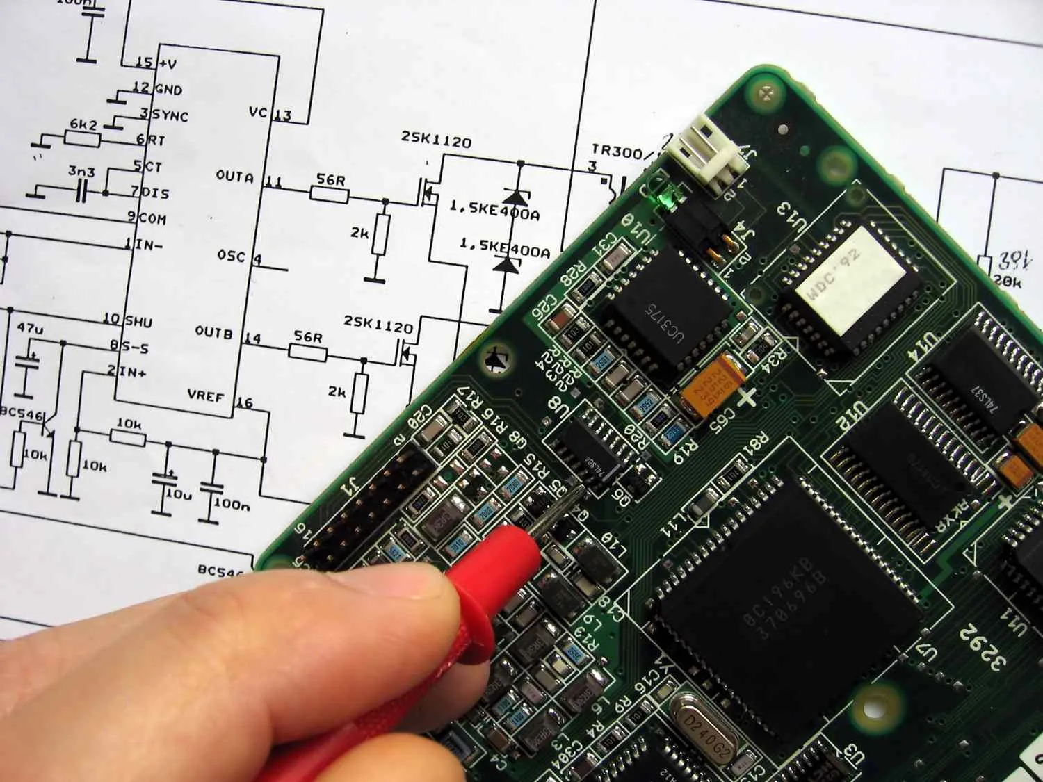
The first time most people look at a circuit schematic, they feel the same thing: a mild panic followed by the quiet suspicion that electronics might not be for them.
It is for them. The schematic just hasn't been properly introduced yet.
A schematic is nothing more than a map — a standardized picture language that describes how electricity moves through a circuit. Once you know the alphabet, you can read any schematic, for any circuit, anywhere in the world. Let's go through it piece by piece.
Start Here: What a Schematic Actually Is
A schematic does not show you what a circuit looks like physically. It doesn't care where components sit on a board or how long the wires are. It only shows you what is connected to what, and in what order.
Think of it like a subway map. The London Underground map doesn't show real distances or exact street positions — it shows relationships. Which station connects to which line. That's all a schematic does for electricity.
The Five Symbols You Must Know First
You don't need to memorize every symbol before you start. You need these five, and the rest will follow naturally.
1. The Battery (or DC Power Supply) Drawn as alternating long and short parallel lines. The long line is the positive terminal (+), the short line is negative (−). This is your source — where energy enters the circuit.
2. The Resistor In US-style schematics (IEEE standard), a resistor is drawn as a jagged zigzag line. In European/IEC-style schematics, it's a plain rectangle. Either way, it represents opposition to current flow — it's a speed bump for electrons.
3. The LED (Light-Emitting Diode) Looks like a triangle pointing into a vertical bar, with two small arrows pointing away from it (representing light). The triangle points in the direction current flows — this matters, because LEDs only work one way.
4. The Switch A line with a gap and a tilted segment — like a lever you can open or close. Open switch = broken path = no current. Closed switch = complete path = current flows.
5. Wire Connections Lines on a schematic are wires. When two lines cross with a filled dot (●), they are connected. When they cross with no dot, they pass over each other without connecting. That dot is tiny but critical — get it wrong and you'll spend an hour debugging a phantom fault.
How to Trace Current Flow: The One Rule That Makes Everything Click
Here is the single most useful habit in reading schematics: always trace the path from positive to negative.
Conventional current (the standard we use in schematics) flows from the positive terminal of the power source, through the circuit components, and back to the negative terminal. This loop — called a closed circuit — is what allows current to flow at all.
Try it with a simple example: imagine a battery, a switch, a resistor, and an LED all connected in series (one after another, in a single loop).
- Start at the positive terminal of the battery.
- Follow the wire — you hit the switch first. If it's open, stop. No current. If it's closed, keep going.
- Next, you reach the resistor. Current passes through, losing some energy (voltage) as it does. This is intentional — it protects the LED from too much current.
- Then comes the LED. Check the triangle direction: is current entering the flat base of the triangle? Good. The LED lights up.
- Finally, the wire returns to the negative terminal of the battery. Circuit complete.
That's it. That walkthrough works for circuits with 4 components or 400.
Parallel vs. Series: The Fork in the Road
Once you're comfortable with a single loop, schematics will introduce parallel branches — places where the circuit splits into two or more paths before rejoining.
In a series circuit, the same current flows through every component in sequence. If one component fails, the whole circuit goes dark (think old-style Christmas lights).
In a parallel circuit, each branch gets the full supply voltage independently. Current divides between branches. If one branch fails, the others keep working — which is why your house lights don't all go out when one bulb blows.
When you see the circuit split, trace each branch separately, as if the other branches don't exist. Then rejoin them where the paths meet again.
A Practical Reading Strategy
When you pick up an unfamiliar schematic, do this before anything else:
- Find the power supply — identify + and −. This orients the whole map.
- Count the branches — how many separate paths exist between power and ground?
- Name each component — resistors usually have an R label (R1, R2), capacitors C, LEDs D. Use those labels as landmarks.
- Trace one branch at a time — follow current from + to − through just that branch, noting what each component does.
- Look for ground symbols — a series of horizontal lines getting shorter (like a triangle made of lines). Ground is the common return path. Every path in the circuit eventually leads here.
The Mindset Shift That Changes Everything
The biggest barrier to reading schematics isn't intelligence or technical knowledge. It's the assumption that the diagram should be obvious at first glance. It won't be — and it doesn't need to be. You trace it. You follow the logic. You let the path reveal itself one step at a time.
Every experienced electronics technician does exactly what you just practiced above. They just do it faster because they've done it a thousand times.
Your first schematic will feel slow. Your tenth will feel manageable. Your fiftieth will feel like reading a sentence.
And it all starts with a battery, a wire, and knowing which way the current flows.
If you want to go from reading schematics to building real, working circuits — component by component, project by project — that's exactly what my Electronics Diploma is built for. No prior experience needed. Just bring the curiosity.